Description du produit
|
Nom du produit |
Truck front lower protection left bracket |
| Méthode de moulage |
Sand casting-clay sand |
| Numéro de modèle |
2857121-DM637 |
| Poids net |
26.5lb |
| Matériel |
Fonte ductile/Norme ISO : 450-10 |
| Norme technique |
Q/CAM-286 |
| Prix EXW |
US$20.4 |
| Spécification | D'après le dessin ou l'échantillon du client. | |
| Poids de moulage | 0,1 kg - 3 tonnes | |
| Norme de moulage | OIN, DIN, AISI, ASTM, BS, JIS, etc. | |
| Tolérance de moulage | CT7-CT8. | |
| Rugosité de surface | Ra0,05-Ra50. | |
| Traitement thermique | Normalisation, recuit, trempe, revenu, etc. | |
| Matériau de moulage | Fonte ductile de haute qualité (QT1050-6)/(QT800-5)/(QT600-5), fonte grise, acier inoxydable, acier au carbone. | |
| Procédé de moulage | Moulage au sable | sable enrobé à base de fer |
| sable enrobé | ||
| sable argileux | ||
| sable résineux | ||
| moulage de précision | ||
| Moulage en mousse perdue | ||
| coulée sous vide | ||
| Préparation de surface | Sablage, placage, galvanisation, peinture au pistolet, passivation, polissage, électrophorèse, usinage, etc. | |
| Équipement d'inspection | Équipements de test : analyseur de spectre, machine à mesurer tridimensionnelle hexagonale, équipement de test de dureté, machine d’essai de traction, équipements de test de revêtement électrolytique, métalloscope. | |
| Inspection dimensionnelle | Machine à mesurer tridimensionnelle (MMT), pied à coulisse, jauge de hauteur, pied à coulisse micrométrique, jauge d'intérieur, jauge d'angle et R, jauge personnalisée, etc. | |
| Application du produit | Nos produits sont largement utilisés dans de nombreux secteurs, tels que l'automobile, les camions, les trains, les chemins de fer, les équipements de fitness, les machines agricoles, les machines minières, les machines pétrolières, les engins de chantier, la construction navale, le bâtiment et autres équipements énergétiques. | |
| Cycle de production d'échantillons | 30 à 45 jours ouvrables. | |
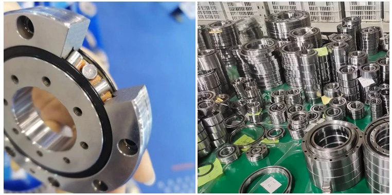
LARGE APPLICATION DES PRODUITS
Les pièces moulées produites par CZPT sont largement utilisées dans divers secteurs industriels, notamment les engins de chantier, les trains, les chemins de fer, les chariots élévateurs, les machines agricoles et autres équipements mécaniques. Nous réalisons tous types de pièces moulées selon les plans et les spécifications de nos clients.
Notre entreprise propose une gamme variée de produits répondant à vos besoins les plus divers. Depuis sa création, nous privilégions la qualité, la satisfaction client et la fiabilité, et nous nous efforçons constamment de répondre aux attentes de nos clients. Face à l'essor irrésistible de la mondialisation économique, nous souhaitons collaborer avec des entreprises du monde entier afin de développer une relation commerciale durable.
1. Êtes-vous une usine ou une société commerciale ? Bénéficiez-vous d’un avantage en termes de prix ?
CZPT est avant tout un fabricant de pièces moulées. Nous proposons un service complet. Les produits achetés par nos clients sont fabriqués directement dans notre usine. Par conséquent, le prix de nos produits est réduit de 51 à 101 TP3T par rapport aux coûts de distribution. Notre prix est nettement plus avantageux.
2. Comment pouvez-vous garantir une livraison à temps ?
Avant chaque nouvelle commande, chaque service organise une réunion afin d'établir un plan de production rigoureux, de mettre en œuvre l'approvisionnement en matières premières, le plan de distribution et de régler d'autres questions. Par ailleurs, notre collaboration avec de grandes entreprises a également permis d'améliorer notre système de livraison.
3. Comment garantissez-vous la qualité de vos produits ?
Tout d'abord, nous effectuons un contrôle qualité rigoureux des matières premières afin de garantir leur conformité. Ensuite, nous procédons aux tests et contrôles nécessaires tout au long de la production. Par ailleurs, les pièces moulées pour camions 70% de la succursale de Hangzhou de China First Auto Work sont fabriquées par Botai, ce qui atteste de la qualité de nos produits.
4. Comment pouvons-nous vous faire un devis ?
Veuillez nous envoyer votre demande par courriel, accompagnée de tous les plans techniques dont vous disposez. Indiquez notamment la nuance du matériau, les tolérances, les exigences d'usinage, le traitement de surface, le traitement thermique, les propriétés mécaniques requises, etc. Notre ingénieur spécialisé étudiera votre demande et vous fournira un devis. Nous vous remercions de votre intérêt et vous répondrons sous 3 à 5 jours ouvrables.
5. À quels secteurs d'activité les produits achetés s'appliquent-ils ?
Nous sommes un fabricant OEM professionnel. Nos produits sont largement utilisés dans les secteurs des chariots élévateurs, des camions, des trains, des machines, des mines, de la construction, de l'agroalimentaire et autres. Nous pouvons fabriquer toute pièce détachée demandée.
How to Replace a Bearing
If you want to select a bearing for a specific application, you should know a few basics. This article will give you an overview of ball, angular contact, and sliding-contact bearings. You can choose a bearing according to the application based on the characteristics of its material and preload. If you are not sure how to choose a bearing, try experimenting with it. The next step is to understand the Z-axis, which is the axes along which the bearing moves.
Z axis
When it comes to replacing your Z axis bearing, there are several things you must know. First, you need to make sure that the bearings are seated correctly. Then, you should check the tension and rotation of each one. To ensure that both bearings are equally tensioned, you should flex the Core to the desired angle. This will keep the Z axis perpendicular to the work surface. To do this, first remove the Z axis bearing from its housing and insert it into the Z axis motor plate. Next, insert the flanged bearing into the Z axis motor plate and secure it with 2 M5x8mm button head cap screws.
Make sure that the bearing plate and the Z Coupler part are flush and have equal spacing. The spacing between the 2 parts is important, as too much spacing will cause the leadscrew to become tight. The screws should be very loose, with the exception of the ones that engage the nylocks. After installing the bearing, the next step is to start the Z axis. Once this is done, you’ll be able to move it around with a stepper.
Contact angulaire
Ball bearings are made with angular contacts that result in an angle between the bearing’s races. While the axial load moves in 1 direction through the bearing, the radial load follows a curved path, tending to separate the races axially. In order to minimize this frictional effect, angular contact bearings are designed with the same contact angle on the inner and outer races. The contact angle must be chosen to match the relative proportions of the axial and radial loads. Generally, a larger contact angle supports a higher axial load, while reducing radial load.
Ball bearings are the most common type of angular contact bearings. Angular contact ball bearings are used in many applications, but their primary purpose is in the spindle of a machine tool. These bearings are suitable for high-speed, precision rotation. Their radial load capacity is proportional to the angular contact angle, so larger contact angles tend to enlarge with speed. Angular contact ball bearings are available in single and double-row configurations.
Angular contact ball bearings are a great choice for applications that involve axial loads and complex shapes. These bearings have raceways on the inner and outer rings and mutual displacement along the axial axis. Their axial load bearing capacity increases as the contact Angle a rises. Angular contact ball bearings can withstand loads up to 5 times their initial weight! For those who are new to bearings, there are many resources online dedicated to the subject.
Despite their complexity, angular contact ball bearings are highly versatile and can be used in a wide range of applications. Their angular contact enables them to withstand moderate radial and thrust loads. Unlike some other bearings, angular contact ball bearings can be positioned in tandem to reduce friction. They also feature a preload mechanism that removes excess play while the bearing is in use.
Angular contact ball bearings are made with different lubricants and cage materials. Standard cages for angular contact ball bearings correspond to Table 1. Some are machined synthetic resins while others are molded polyamide. These cage materials are used to further enhance the bearing’s axial load capacity. Further, angular contact ball bearings can withstand high speeds and radial loads. Compared to radial contact ball bearings, angular contact ball bearings offer the greatest flexibility.
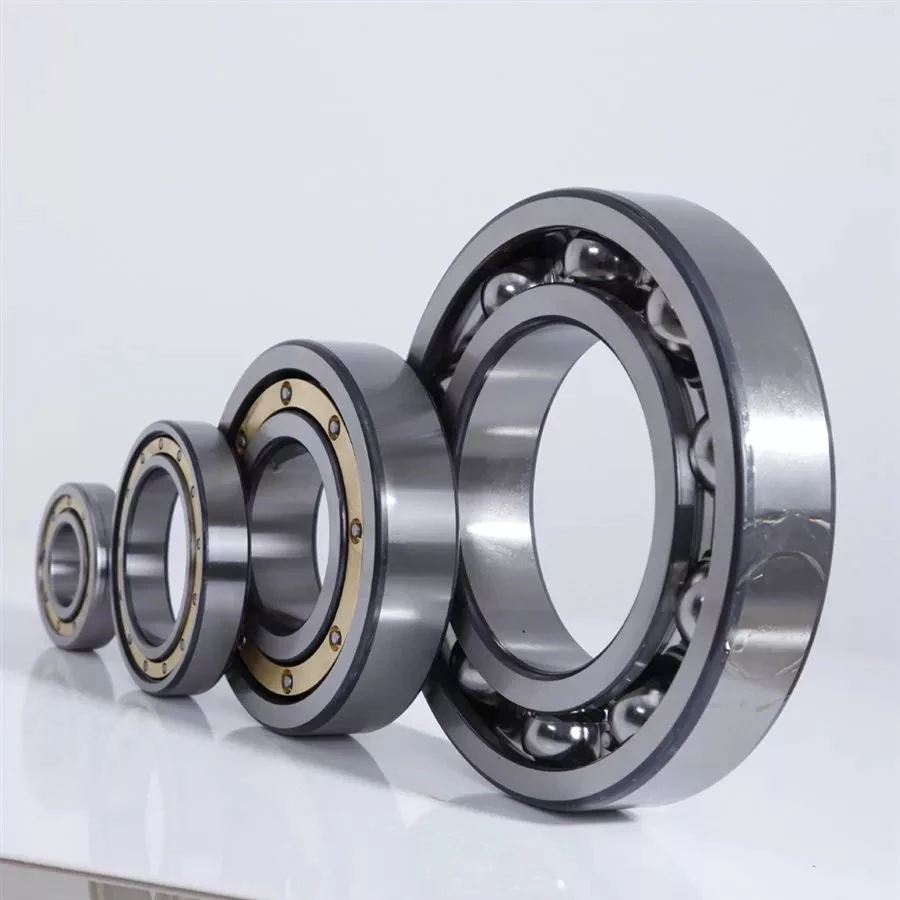
Ball bearings
Ball bearings are circular structures with 2 separate rings. The smaller ring is mounted on a shaft. The inner ring has a groove on the outer diameter that acts as a path for the balls. Both the inner and outer ring surfaces are finished with very high precision and tolerance. The outer ring is the circular structure with the rolling elements. These elements can take many forms. The inner and outer races are generally made of steel or ceramic.
Silicon nitride ceramic balls have good corrosion resistance and lightweight, but are more expensive than aluminum oxide balls. They also exhibit an insulating effect and are self-lubricating. Silicon nitride is also suitable for high-temperature environments. However, this type of material has the disadvantage of wearing out rapidly and is prone to cracking and shattering, as is the case with bearing steel and glass. It’s also less resistant to heat than aluminum oxide, so it’s best to buy aluminum nitride or ceramic ball bearings for applications that are subjected to extremely high temperatures.
Another type of ball bearings is the thrust bearing. It has a special design that accommodates forces in both axial and radial directions. It is also called a bidirectional bearing because its races are side-by-side. Axial ball bearings use a side-by-side design, and axial balls are used when the loads are transmitted through the wheel. However, they have poor axial support and are prone to separating during heavy radial loads.
The basic idea behind ball bearings is to reduce friction. By reducing friction, you’ll be able to transfer more energy, have less erosion, and improve the life of your machine. With today’s advances in technology, ball bearings can perform better than ever before. From iron to steel to plastics, the materials used in bearings have improved dramatically. Bearings may also incorporate an electromagnetic field. So, it’s best to select the right 1 for your machine.
The life expectancy of ball bearings depends on many factors, including the operating speed, lubrication, and temperature. A single million-rpm ball bearing can handle between 1 and 5 million rotations. As long as its surface contact area is as small as possible, it’s likely to be serviceable for at least 1 million rotations. However, the average lifespan of ball bearings depends on the application and operating conditions. Fortunately, most bearings can handle a million or more rotations before they start showing signs of fatigue.
Sliding-contact bearings
The basic principle behind sliding-contact bearings is that 2 surfaces move in contact with 1 another. This type of bearing works best in situations where the surfaces are made of dissimilar materials. For instance, a steel shaft shouldn’t run in a bronze-lined bore, or vice versa. Instead, 1 element should be harder than the other, since wear would concentrate in that area. In addition, abrasive particles tend to force themselves into the softer surface, causing a groove to wear in that part.
Sliding-contact bearings have low coefficients of friction and are commonly used in low-speed applications. Unlike ball and roller bearings, sliding contact bearings have to be lubricated on both sides of the contacting surfaces to minimize wear and tear. Sliding-contact bearings generally are made of ceramics, brass, and polymers. Because of their lower friction, they are less accurate than rolling-element bearings.
Sliding-contact bearings are also known as plain or sleeve bearings. They have a sliding motion between their 2 surfaces, which is reduced by lubrication. This type of bearing is often used in rotary applications and as guide mechanisms. In addition to providing sliding action, sliding-contact bearings are self-lubricating and have high load-carrying capacities. They are typically available in 2 different types: plain bearings and thrust bearings.
Sliding-contact linear bearing systems consist of a moving structure (called the carriage or slide) and the surfaces on which the 2 elements slide. The surfaces on which the bearing and journal move are called rails, ways, or guides. A bore hole is a complex geometry, and a minimum oil film thickness h0 is usually used at the line of centers. It is possible to have a sliding-contact bearing in a pillow block.
Because these bearings are porous, they can absorb 15 to 30% of the lubrication oil. This material is commonly used in automobile and machine tools. Many non-metallic materials are used as bearings. One example is rubber, which offers excellent shock absorbency and embeddability. While rubber has poor strength and thermal conductivity, it is commonly used in deep-well pumps and centrifugal pumps. This material has high impact strength, but is not as rigid as steel.


