Why PTO Shaft Length Adjustment Is a Safety Procedure
PTO shaft length adjustment is not a casual fit-and-forget task. A shaft set to the wrong length creates risks at both extremes: too short and the telescoping sections disengage under load, releasing a spinning driveline with no predictable trajectory; too long and the sections bottom out during implement raise, transmitting compressive force into the tractor stub shaft and implement gearbox input bearing — both of which are designed for torque, not axial load. Either failure mode can cause equipment damage and serious injury.
This step-by-step guide covers the complete length adjustment procedure from initial measurement through safe testing, with specific guidance for new tractor-implement combinations and for existing shafts being moved between machines.
Before You Start: What You Need
Gather the following before beginning the procedure: a measuring tape or long ruler, a marker or paint pen, an angle grinder with cutting disc (if shortening is required), a file or deburring tool, a torque wrench for yoke pinch bolts if fitted, and the implement’s operator manual for minimum overlap and joint angle specifications. If the implement manual is unavailable, use the general safety limits covered in this guide — they apply to the vast majority of standard agricultural PTO shafts.
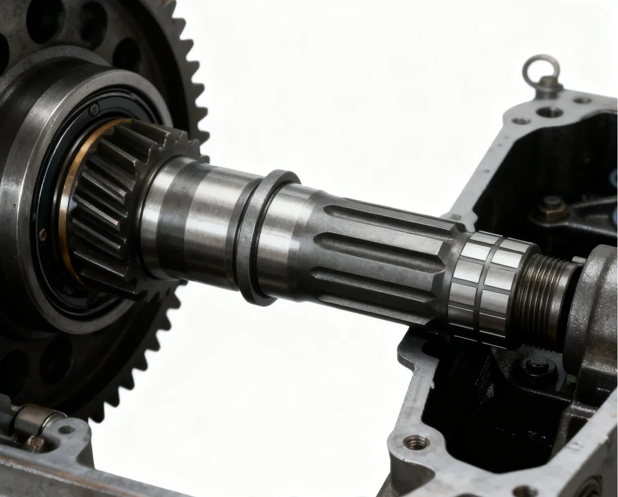
Step 1 — Measure in the Raised Position First
Connect the implement to the tractor with the 3 point hitch and raise it to the maximum transport height — the position where tractor-to-implement distance is at its shortest. Separate the two shaft halves and hold them together with the implement raised. Push them fully together and mark where the inner tube enters the outer tube. The gap between this mark and the end of the outer tube shows how much compression travel is available. There must be at least 25 mm (1 inch) of remaining compression travel with the implement at maximum height. Less than this will cause bottoming out.
Step 2 — Measure in the Lowered Working Position
Lower the implement to the maximum working depth — the deepest position it will reach during field operation. Extend the shaft fully and hold the two halves at the distance required to reach both yokes. Mark the overlap — the length of inner tube remaining inside the outer tube at this maximum extension. The minimum safe overlap is 150 mm (6 inches). If the overlap in the lowered position falls below this, the shaft is too short and a longer unit is required — do not attempt to cut and extend a PTO shaft, as this compromises structural integrity and voids any safety rating.
Minimum 25 mm compression travel must remain. If the shaft bottoms out before full raise height, the shaft is too long and must be shortened.
Minimum 150 mm overlap must remain. If this isn’t met at maximum extension, the shaft is too short — replace with a longer unit.
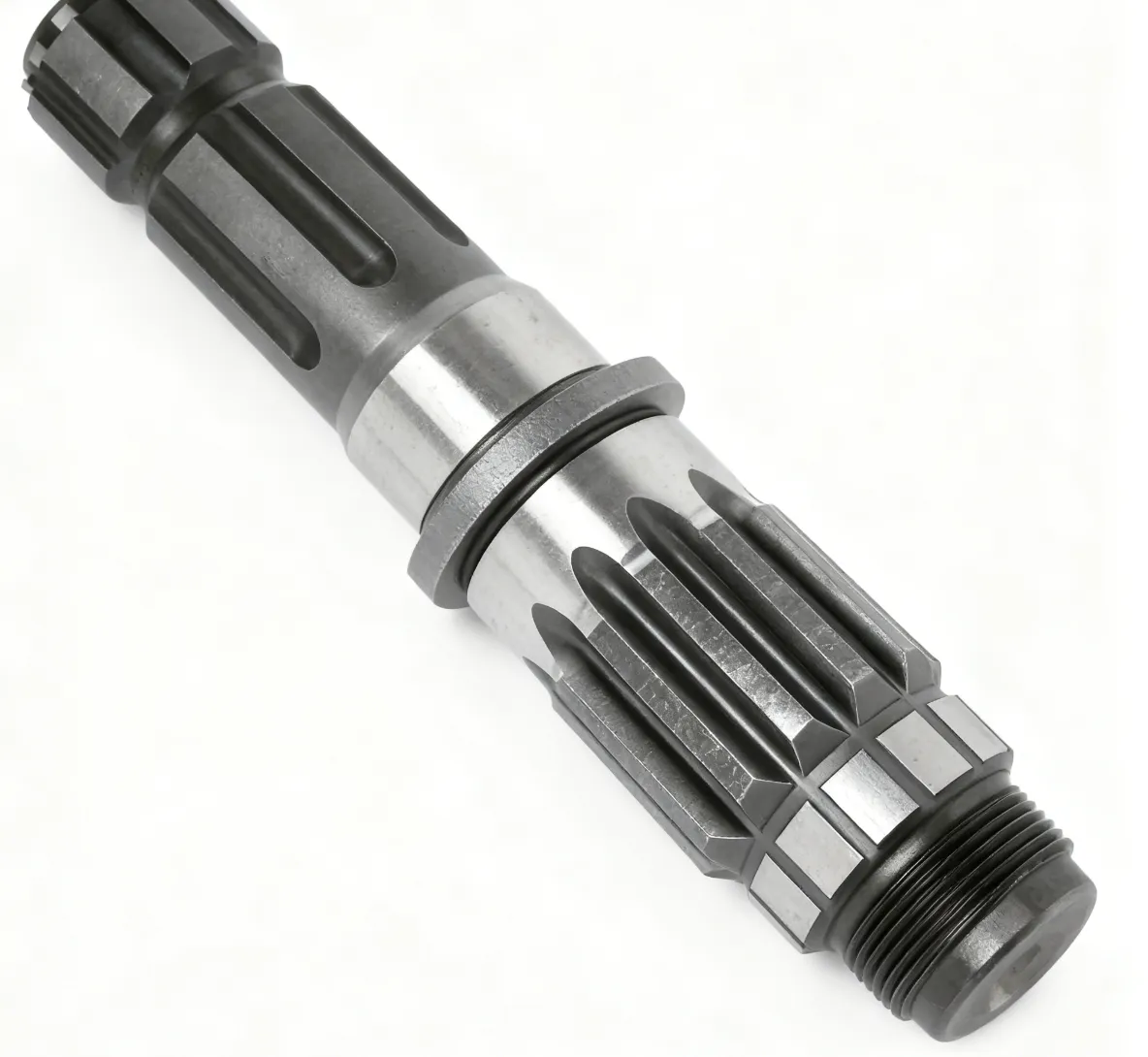
Step 3 — Shortening the Shaft if Required
If the raised position check shows insufficient compression travel, the shaft must be shortened. This is safe to do correctly — it is the standard factory-intended adjustment on new shafts. Follow this procedure:
Separate the inner and outer shaft tubes. Calculate how much must be removed: the amount by which the shaft bottomed out, plus the required 25 mm safety clearance. Mark equal amounts on both the inner tube and outer tube — both must be shortened by the same amount to preserve the overlap ratio throughout the travel range.
Use an angle grinder with a cutting disc. Cut perpendicular to the tube axis — an angled cut creates uneven telescope engagement. Always keep the shield guard attached and wear face protection and gloves. Cut the outer profile tube first, then the inner triangular or lemon-section tube.
File or grind all cut edges smooth — burrs and sharp edges on the tube ends will tear the profile bearing or plastic inner guide during telescope operation. Apply fresh grease to the inner tube profile section before reassembly. The shield must also be trimmed by the same amount as the tube it covers.
Reassemble the shaft and repeat both the raised-position and lowered-position checks from the start of this guide. Both limits must now be satisfied. Do not connect to PTO until both checks pass.
Step 4 — Check the Shield Coverage and Refit
The rotating guard shield must cover the full length of both the inner and outer tube at all positions throughout the hitch travel range. If the shaft was shortened, the shield must be shortened by the same amount — a shield that extends beyond the tube end creates a rotating hazard at the exposed end. Check that the shield end caps or funnel guards are secure and rotate freely around the tubes in both compressed and extended positions. Fit the shield chain to the implement bracket to prevent the shield from rotating with the shaft.
Step 5 — First Run Test Procedure
After completing the length adjustment and shield check, connect the shaft to the tractor and implement in normal operating position. Before engaging the PTO, move away from the shaft and implement by at least 3 meters. Engage the PTO at the lowest throttle setting and observe the shaft through one full cycle of raise and lower. Look for any contact between the shield and nearby components, listen for rubbing or irregular noise, and confirm the shaft does not appear to strain at either extreme of travel. Only after this check is it safe to advance to full operating speed and load.
For detailed guidance on PTO shaft selection, torque ratings, and wide-angle applications, consult this PTO shaft selection guide for additional technical specifications.
Need a Replacement PTO Shaft?
PRR Tractor Part stocks PTO shaft assemblies in standard collapsed lengths for 540 and 1000 RPM applications — both standard cross-joint and wide-angle CV configurations available.
Domande frequenti
PTO Shafts Matched to Your Setup
540 and 1000 RPM shafts in standard and wide-angle configurations — contact us with your measurements for a confirmed fit.
PRR Tractor Part Limited Partnership | [email protected]
304/1170 Soi Phahonyothin 49/1, Intersezione 6, sottodistretto di Talat Bang Khen, distretto di Lak Si


